
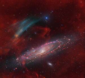
Discovery of the M31 [OIII] emission arc
Recently, a major discovery by an international team of amateur astronomers and scientists has become a huge online hit, and this new discovery is just located in one of the
Do you feel upset when you find the guiding error is so high at imaging night? Do you have frustrating idea of sending the mount back to the factory during gear tuning?
In this article ZWO AM5 mount review, the author Ya Ge will share what he learned about how to improve guiding quality systematically. And it will definitely benifit you as well!
Recently ZWO sent me an AM5 EQ mount for review. During the first light, I surprisingly found the guiding error (RMS) reached 1.41 arc sec. This is a ridiculous amount of error and I thought either AM5 is a total piece of trash or ZWO sent me a lemon. Being upset of the first light, I mounted the same gears on my Rainbow Astro RST-135e (the one with autoencoder), and pointed it to the same region of the sky, expecting it gets an error of 0.3+ arc sec. However, when I was getting ready to take a screenshot and send it to the ZWO group to humiliate AM5, I found phd2 gave me an error of 1.19 arc sec. This is when I realized something is off here. I trust my RST-135e and it shouldn’t have an error like this. Realizing I may have had quite some misconceptions on guiding, I spent about 30 hours on experiments and measurement, and learned a lot. Eventually I was able to make the same RST-135e consistently have a guiding error of 0.3+ arc sec, and the same AM5 0.4+ arc sec. Both could give good 30min exposures on a 530mm scope. And in this post, I’d like to share what I learned, and hope it could benefit the community as well.

Figure 1. AM5 reaching a guiding RMS of 0.47 arc sec in a 2+ hours interval. More details of the configurations can be viewed in the top right “Section Heading” section.
But before I introduce specific technical factors, I wanted to talk about the methodology, which is potentially more important. The reason why astrophotography is so hard is it involves too many factors. The same applies to the mount system. In order to achieve pinpoint stars, one needs to spend a lot of time and effort on the Polar Alignment, mechanical strength, guide scope/OAG, algorithm tuning, and of course the mount itself. This is a complicated system, and could easily drive one crazy — contradictory measurements, hours of time ending up with no improvement, applying popular suggestions online and found they didn’t work… This is normal, and is part of astrophotography.
Make sure pinpoint stars are actually important for you. For example, I was mainly interested in wide field mosaics, in which case the stars would be dramatically downsampled in the final mosaic. So I didn’t care guiding and this saves me from this miserable process, until this review. I was just suspicious on the fact that the AM5 has a close RMS comparing with the RST-135e and wanted to figure out what’s going on. And that’s what motivated me to do all the experiments.
And we are now ready to dive deep into the technical factors which affect the guiding accuracy and the shape of the stars. I will also provide methods to quickly cross check whether each factor is the cause, and how to fix it if it’s the case.

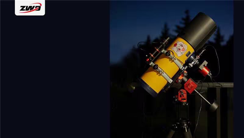
Figure 2. ZWO AM5 EQ mount on a TC40 tripod and a 2nd gen half pier, showing one of the testing gears in this review.
An often overlooked factor in the mount system is the tripod. The major impact of the tripod is the polar alignment when the scope points to different directions, which is caused by the subtle deform of the tripod. The popular carbon fiber tripods are indeed stiff and solid. We often see demos of an adult standing on top of it. But on one hand, astrophotography has much higher requirements on precision, to the arc minute level, than regular photography. And on the other hand, the unique property that strain wave mounts don’t require balancing gives extra challenges on the tripod. The lack of counterweights and balance means the center of gravity is no longer always kept above the center of the tripod. Instead, it will shift around when the scope moves. This brings a new type of deform and thus requires new tests to the tripod.

Figure 3. A TC40 tripod with steel feet
The test of tripods is relatively easy. When we use tools like ASIAir or SharpCap Pro to do polar alignment, it will show a alignment error after the RA axis rotates. We could start from the home position (pointing to the Polaris, right above the tripod), turn the RA axis 90 degrees to the west to do the polar alignment, and take notes of the remaining alignment error. After that, we start from the home position again, but turn the RA axis 90 degrees to the east to check the alignment error. (For ASIAir, because we can only rotate the RA axis to the west, we can start from the east-most position, and rotate 90 degrees to the home position) When the tripod is an ideal rigid body, we should observe the same alignment error both sides. And when the tripod has deformation, the alignment error would be different. My testing shows that if we mount a SharpStar 13028HNT without a counterweight, RT90C shows 8 arc minutes’ difference in alignment error, and TC40 shows only 2 arc minutes. Note using counterweights would impact this difference as well. The better balance one gets, the less movement the center of gravity there is. And this will reduce the polar alignment shift. Furthermore, not only the carbon fiber tubes could deform, the feet could also deform. I found the rubber feet of RT90C pretty soft. I could introduce decent deformation by hands. TC40 has harder feet but still not ideal. It’s said that steel feet like those from SuperMount could bring quite some improvement, but it also comes with a premium.
If one really gets error in polar alignment, the result would be field rotation. Field rotation cannot be removed by guiding. Because the movement can be decomposed into two parts, a global translation, which could be corrected by guiding, and a rotational movement surrounding the center of the field of view. This part can only be corrected by rotating the camera, and goes beyond the capabilities of the guiding system. In this case, one may get a decent guiding error but still have trailing stars, especially on long exposures, which is the indicator of a polar alignment issue.
One important benefit from strain wave drives is that balancing is not required any more. My observation is that, moving the scope along the DEC axis for about 8 inches only worsened the guiding error by 0.2 arc sec, which could even be pure measurement error. There is some anecdotal evidence that the strain wave drives could benefit from an intentionally unbalanced setting, which resulted as a smaller Periodic Error (PE). Unfortunately I was not able to verify this using experiments. For example, when I use a 13028HNT with a counterweight pointing to the celestial equator, the AM5 at my hand had a PE of 20 arc sec measured in a 15 minutes interval. And the guiding RMS is around 0.9 arc seconds. But at roughly the same time, using the same gear pointing to the same direction, removing the counterweights won’t change the measured PE, only reducing the guiding error to 0.7 arc seconds. I have a possible explanation that, although the PE didn’t decrease when we removed the counterweight, this effectively reduced the rotational inertia. From a control theory perspective, this makes the guiding system more responsive and easier to stabilize. Especially considering strain wave drives usually require high frequency guiding (0.5~1 seconds exposure), this is very helpful and may end up with a smaller guiding error. Therefore, we see a trade off here. Removing the counterweights could practically improve the guiding, but also poses more challenges on the tripod’s stiffness, potentially causing polar alignment issues and even tip over. So it really depends on the personal preferences on the risk. For conservative users, using counterweights will ensure the gears won’t get tip over, at a cost of slightly larger guiding error. For users seeking perfect tracking, an actual testing on the boundary of the system may be desired.
Guide scopes and OAGs are a critical component of a guiding system. Generally they need to satisfy two requirements, matched resolution and mechanical stiffness. Matched resolution means the per pixel resolution in arc seconds shouldn’t be too far away between the guide scope system and the main scope system. Popular online opinions state the guiding system should have at least 1/3 per-pixel resolution of the main scope system, although I didn’t experiment with this. The stiffness means the connection between the guide scope and the main scope should be rigid. Ideally, when the main scope rotates by 1 arc sec, the guide scope should rotate by the same amount at the same time, instead of gradually stabilizing to the equilibrium, which obviously would impact guiding accuracy. That’s also why OAG is preferred when able to — it solves both issues, and also saves a heated dew shield.
But what I really wanted to talk about is the optical quality of the guide scope or OAG. Conventionally it’s thought to be unimportant to have pinpoint stars for guide scopes. And that’s why on one hand most guide scopes are achromatic instead of apochromatic, and on the other hand there are sayings that it may be even better if one intentionally bring focus error to the guide scope. However, my experiments said otherwise. My guide scope is a SharpStar FMA180, which has a reducer-flattener. It has a focal length of 220mm and mediocre star shape when used without the reducer. And with the reducer, it becomes a 180mm focal length APO with pinpoint stars. With all the other settings the same, once I mounted the reducer (don’t forget to change the focal length in the phd settings), it’s immediately obvious that the HFR reported by phd became smaller in arc seconds, and the guiding RMS also got lower. After discussing with experienced photographers, we have an assumption that this is because when the stars’ energy get more concentrated, phd could localize the center of star mass more reliably and robustly, and thus gives more precise corrections. We also have a surprising finding that when we use guide scopes with so-so optical quality, turning on bin2 in the phd settings will effectively improve both the guiding quality and the HFR of the exposure from the main scope. Multiple people verified this using different gears. One possible explanation is, the center of star mass can also be localized more reliably in bin2 guiding. Under the condition that the per-pixel resolution still falls in an acceptable range, the guiding could be improved. Overall, if a high quality guiding is desired, it’s still recommended to use an APO guide scope, and connect it with the main scope in a stiff manner. If the imaging scope of the main scope is large enough and proper back focus could be figured out, OAG is also a great option.
One would easily find out that the guiding quality is significantly affected by the choice of guiding algorithms and their parameters. There is a simple way to get a base setting for those algorithm choices — the phd Guiding Assistant would recommend a good setting by measuring a bunch of important specs of the guiding system. Some other tricks include, sometimes phd would complain that the RA and DEC correction rate varied too much, and this could be solved by calibrating with the scope pointing near the celestial equator. The error of RA and DEC axes not perpendicular could be caused by seeing (more likely) or backlash (less likely for strain wave mounts), and in most cases, increasing guiding exposure could solve the issue. There are online suggestions that the guiding rate (not guiding exposure) may affect guiding accuracy. But my experiments on AM5 didn’t confirm this. 0.5x and 1.0x guiding rates yield pretty similar guiding error. But for mounts with encoders like RST-135e, setting the guiding rate to 0.1x~0.3x seems to help. In general, the backlash of strain wave drives are very small. In the case that Guiding Assistant gives a large backlash (e.g. >200ms) and the DEC axis is hard to stabilize, we could override the settings to use a smaller backlash compensation, or disable it completely.
A very important parameter is guiding exposure, which deserves a separate discussion here. To understand its impact, we need to introduce the periodic error of EQ mounts. No matter whether it’s a traditional worm gear mount, or the strain wave gear mount, there is a periodic error. Specifically, in the process of the gear rotates one revolution, the angular speed is not absolutely even. Sometimes it goes slightly faster, sometimes slightly slower. If we take a look at the RA axis of an unguided mount, the stars would turn east a bit sometimes, and west a bit sometimes. This error is cyclic, whose period is the time the drive rotates one revolution. What guiding does is to correct this periodic error (PE) in real time. So what really matters for the guiding accuracy is not the absolute scale of the PE, but the slope of it, or how fast the location of the stars change. If the stars move too far in a short time, the guiding system cannot keep up with it, which will result in trailed stars. If the PE is accurate across cycles, it’s possible to record and playback the error (in negative magnitude), which is the PE Correction feature of conventional EQ mounts. Unfortunately, the PE of strain wave mounts have three properties: large in magnitude, steep in slope, and not accurately repeatable across cycles. Therefore, PE Correction is not an option for strain wave mounts. As we analyzed above, large PE magnitude isn’t really an issue, but for the steep slope, we need a different strategy to set the guiding parameters. Specifically we need short exposures. This allows the guiding system to correct the PE frequently, such that the magnitude of each correction is still well within its capability. For AM5 and RST-135 (without autoencoders), I found 0.5s or 1.0s work the best. But RST-135e works better for 2~3 seconds exposure, probably because it’s auto encoder brings very small (5 arc secs) and smooth PE. However, short exposure will also bring another problem, i.e. the guiding will run after the atmosphere turbulence instead of the real star movement. Therefore, for the strain wave mounts, if the seeing is bad, the guiding will degrade to a larger extent comparing with its sisters with autoencoders. Enabling multi-star guiding in phd would help alleviate this issue.
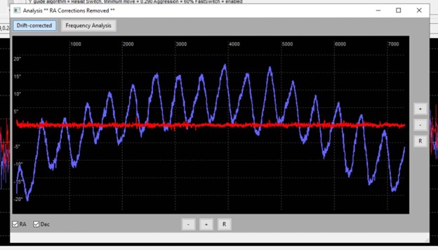
Figure 4. The Periodic Error of the AM5 in the same time interval shown in Figure 1. We can see the PE reaches 20 arc secs, which is worse than traditional worm gear mounts. But it doesn’t prevent us from getting similar high quality guiding, if the parameters are properly set.
One thing that most EQ mount review doesn’t mention is which direction the scope is pointing to. This actually has a substantial impact on the guiding error. The table below shows the data I measured using RST-135e in a relatively short period. If we fix the RA such that the scope roughly points to the zenith, and change the DEC, we could measure the guiding error in the different angles. We can easily see the errors varied by 2~3 times in different DECs. This could be caused by multiple factors. One one hand, the mount has different effective angular loads in different poses, which may cause different PE slopes. It’s possible that the mount has the smoothest PE when it’s pointed to the zenith. On the other hand, the atmosphere that the photons need to penetrate is thinner when the scope is pointing closer to the zenith. So the seeing is better, which would also benefit the guiding.
| DEC (degree) | Angle to zenith (degree) | RA guiding error (arc sec) | DEC guiding error (arc sec) | Overall guiding error (arc sec) |
| 0 | -50 | 1.04 | 0.81 | 1.32 |
| 10 | -40 | 0.88 | 0.76 | 1.17 |
| 20 | -30 | 0.54 | 0.31 | 0.63 |
| 30 | -20 | 0.47 | 0.41 | 0.60 |
| 40 | -10 | 0.24 | 0.38 | 0.45 |
| 50 | 0 | 0.23 | 0.30 | 0.38 |
| 60 | 10 | 0.32 | 0.33 | 0.46 |
| 70 | 20 | 0.35 | 0.60 | 0.70 |
Overall, I wanted to emphasize two points. First, it has limited value when we see a screenshot of phd guiding curve without any context in a mount review. Which direction the scope points to, which tripod is used, how optically well is the guide scope, what parameters are used in the guiding algorithms, how good is the seeing, etc. etc. There are too many factors that could make two screenshots not directly comparable. The more scientific way of doing that is, to use the same gears (except the mount), at the same time and place, pointing to the same direction, and compare. Second, guiding is a very complicated system. It’s hard, but with controlled variables, agile cross checks, and scientific attitude to design experiments and track down root cause even when frustrated, it could be learned.
Coming back to AM5. After I adjusted the aforementioned factors one by one, I was surprised that at least for short focal length systems (I was using 530mm FL Takahashi Epsilon 160ed for this test), AM5 could achieve pretty similar performance with RST-135e, which is 3x the price. In my test across three nights, RST-135e could reliably achieve 0.3+ arc sec’s guiding RMS and 2.5+ pixel’s HFR. Using the same tripod, scope, guiding system, directions, at the same location and roughly the same time, AM5 could achieve 0.4+ arc sec’s guiding RMS, and 2.6+ pixel’s HFR. I also tested the HFR of 5min, 10min, and 30min’s exposure on AM5, and can hardly spot differences in the numbers. To make sure the performance is repeatable, I also checked the phd log after shooting overnight, and found it’s pretty stable (see Figure 1). If you are in the same mount chat group with me, you would know that I’m quite suspicious on this observation, and spent a lot of time on tweaking RST-135e, on both hardware and software. Eventually I was able to consistently get 0.3+ arc sec on RST-135e, which I believe is a very reasonable performance, and is even comparable with big traditional brands like AP (models without autoencoders). But after I applied the same optimization to AM5, it could also consistently achieve 0.4+ arc sec. I also once suspected that this AM5 is dedicatedly picked by ZWO for reviewers. But after I asked for people’s inspection reports in the AM5 group, I found actually the mount I received is on the worse side in terms of PE. The only exception is if we calculate the theoretically maximum slope using the zoomed in PE curve, mine is a bit on the better side. Overall, after tens of hours’ picky tests and cross checks, I finally accepted this conclusion that AM5 is indeed quite similar to RST-135e, and would like to recommend AM5 without reservation. At least the AM5 at my hand (AM5 + TC40 tripod + 2nd gen half pier) is an excellent strain wave mount system, with very strong measured specs. I’m also very interested in where is its limit. But I don’t have long FL scope at hand. I may do another test when my customized Dreamscope RC arrives, and compare it with RST-135e again.
Recently, a major discovery by an international team of amateur astronomers and scientists has become a huge online hit, and this new discovery is just located in one of the
Tracy Cao is a 45-year-old stay-at-home mom based in Pleasanton, California, who discovered her passion for astrophotography in the summer of 2021. Although she is relatively new to the industry,
“My Name is Willie Stickley (@WillieHustles) and I am a 26 year old photographer and videographer from Cleveland, Ohio (United States) and I am the current Vice President of the
Guillermo Cervantes Mosqueda is an astrophotographer lives in Poncitlán, Jalisco, Mexico, whose fascination with the night sky began with astronomy books in his childhood. His journey officially took flight in
Being an astrophotographer is the most romantic job in the world. But behind that romance lies a canvas of isolation and peril.From standing helpless and alone at the Baima Snow
Peter Ambrose lives in Porirua, Wellington, New Zealand, after moving there from his hometown of Christchurch in 1991. Now retired from corporate life for over 13 years, he has been